
FreeCad Paths
I’ve been using FreeCad to create STL files for 3D Printing for a long time. It’s a good tool with a some quirks but mostly lets me do what I want without too much trouble. So I’ve been happy with it more or less. I recently discovered it can also create g-code for CNCs with the Path Workbench. I’ve used Carbide Create in the past and was
eager to see how easy FreeCad is to work with. This post is based on the notes I took while learning how to use the Path Workbench.
WARNING My CNC is currently not working, so I haven’t tried the paths created in these tests. I am not an expert at FreeCad or CNC. Use any information presented here at your own risk.
Create an Object
Nearly all of the tutorials I’ve seen show paths carving out flat shapes and drilling holes in the stock.
1. Select Part Design Workbench  2. Create a new document with the
 Create New button or File > New menu.  3. Click on
 Create Body followed by Create Sketch 
 4. In the sketch draw a rectangle define the shape of your body. How you center your sketch might depend on your CNC. I believe mine starts at 0,0 and works in the positive X and Y directions. So I select the XY-plane for the sketch.
  5. For my test I just want a simple rectangle with some simple features added to it. I switched to the
 Sketcher workbench and added a 254 x 114.3 mm rectangle to it.
 6. I use the
 Pad operation to set the height of the object to 31.75mm.  7. I want to create a curved face on the top of the object. To do this I select a side face and press
 Create Sketch.
8. I used the B-Spline tool and a line to create a curve.  9. And cut it out of the box with the Pocket tool.
I also added a square to the top and made a 5mm deep pocket with it.
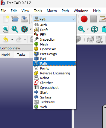
Path Workbench
We use the Path Workbench to create tool paths. When I select Paths, I get a warning: > The currently selected unit schema: > ‘Standard (mm, kg, s, degree)’ > Does not use ‘minutes’ for velocity values.
Velocity is needed when specifying how quickly the tools will move through the paths. So we should set this by editing the Unit Systems value. To do this 1. Go to Edit > Preferences menu to open the preferences dialog 2. In the General Tab set your Unit System to Metric small parts & CNC(mm, mm/min)  3. Press
 OK to close it.
Creating a Tool
FreeCad’s Path Workbench comes with a set of pre-defined tools. These probably won’t be the same specs as our end-mills. So we need to define tools that match our sets.
In the Path menu select
Toolbit Library editor

This will open a Directory dialog. Select the directory where you want to store the library and press
OK. From Here FreeCad will ask you a series of questions.
It proceeds to ask to set up a * Toolbit working directory * Bit directory, a Shape Directory Just say yes to these. I also said yes to Copy example files to the new Bit directory andCopy example files to the new Library directory
Once finished, you’ll see list of Default tools. To add your own bit press the
Create Toolbitbutton
FreeCad will ask you to select a
Tool Shape. They list several different types. For this post I’ll go with the Endmill
Set the name you want to save your endmill to:
 it will show up in the list as a new toolbit
Double click on the tool to edit its properties You can use the
Shapetab to edit the physical dimensions of the bit. * diameter * cutting edge height ( the bit part ) * shank diameter
The Attributes tab lets you edit other properties such as Material and Spindle Direction. 
edit as needed and press OK to save your edits
Press Close to close the toolbit library editor
Path Job
Once you have your tools defined, you can create Jobs. You use jobs to define the paths you want your CNC to follow.
- If you’re not already in the path workbench, Select the
Pathworkbench. from the tool bar - Press the
Jobbutton ( or selectPath > jobmenu) This brings up the
 Create Jobwindow. You can use this window to select the body you want the job to apply to. In this case, there’s only one body so it’s already selected for us.
 NOTE I’m new to the Path Workbench so I don’t have a template yet. I’ll look into it and make another post someday.
press OK
- The
Combo Viewnow shows aJob Editsection and defaults to theSetuptab. Use theStockgroup to define your stock. The default isExtend model's Bounding Boxwhich seems good place to start.
 I extended the stock out a bit for the simulation.
Once your job is setup, you can add operations to it.
Pocket Shape Operation
A fairly basic operation is the Pocket Shape operation. This creates paths to carve out a pocket in your stock.
To add a Pocket Shape 1. Select the face you wish to apply the Pocket Shape to.  2. Press the
 Pocket Shape button ( or select Path > Pocket Shape )  3. The
 Combo view now shows the properties for the Pocket Shape operation. Of interest are the Depths section. This appear to be set correctly by default. The height of my object was 31.750 and the pocket was 5mm deep.  NOTE The Depths are greyed out, but can be edited by pressing the formula button. 4. The
 Operation section is where you define the path taken by your tool.
- The
Patterndetermines how the tool will be moved through the stock.ZigZagis the default. - The
Angleis the angle in which the Zig Zag pattern is applied to the stock. By default this is 45 degrees. - The
StepOverdetermines how far the tool moves for each line in the pattern. It defaults to 100%. At 100% the tool won’t overlap as it passes through your stock material. You may want this lower than 100% depending on your job.
Press Apply to show shows the path the tool will take in the 3D view. (green lines) 
press OK to complete the operation.
FreeCad lets you simulate the operation so you can see what your stock might look like after the operations complete.
- Press the
CAM Simulatorbutton:
- The 3D view adds the stock and the
Combo Viewshows thePath Simulatorcontrols. The controls are similar to a video player. You can stop, play, pause, and fast forward the simulation. Press the
 Playbutton to simulate the operation. It will show the tool as it moves through the stock


The results are pretty jagged.
 With a step-size of 100, the edges of the pocket will be shaped like the endmill. We can fix this by editing the
 Pocket Shape parameters.
- To edit the parameters go to the
Combo Viewand expandJob > Operationsin my case I see thePocket Shapejob
- Double click on
Pocket Shapeto get back to its editor. - In the operation section change the
Pattern:toZigZagOffset, pressApply, and pressOK
- Run the simulation again. The simulation results look much better
 The sides are now smooth.
Unfortunately, there’s another potential problem with my path. The tool is immediately plunged 5mm into the stock and does the zig-zag at this depth. This might work. It depends on the material and the CNC you’re using. You’ll want to remove harder materials layer by layer. We can do this by editing the Step Down value.
- Go to the
Combo Viewand expandJob > Operations - Double click on
Pocket Shapeto get back to its editor - In the
DepthssectionStep Downtext box is disabled by default. Click theFormula Editorbutton to edit it.
Step Downvalue in theFormula Editor. I went with 0.2 mm for this test.

The tool path now covers multiple layers 
NOTE The actual values you use will depend on a number of factors. You should familiarize yourself with your CNC machine and the materials you’re using in order to pick appropriate settings
Pocket3D Operation
There’s a also a curved section in my model that I’d like to cut out. It’s not flat, so Pocket Shape won’t create usable paths for it. Instead I’ll use the 3D Pocket operation
NOTE You may want to hide or remove the Cut Material from the Job to see what you’re doing. Select it and press Space to hide and Delete to remove it
- Select the
Faceyou want to cut. I selected the curved face I made earlier:
- Press the
3D Pocketbutton in the toolbar. This opens thePocket3Dsettings in theCombo View
- This time around, I’m going to edit the
Step DownandPatternsettings immediately.
I set the Step Down in Depths to 0.5 mm  I also set
 Pattern to ZigZagOffset in Operation.  When I pressed
 Apply and the resulting path looks pretty reasonable 
Running the simulation shows the cut follows the general shape of the curved surface.  It has a stair step pattern to it that can probably be smoothed out in post processing and possibly by decreasing the
 Step Down size.
Profile Operation
This is good so far, but in order to be useful, we want the paths to also cut our model out from the stock. This can be done with the Profile operation
- Press the
Profilebutton in the toolbar. This opens aProfileoperation in theCombo View.
- Depending on your material and your CNC machine, you may want to adjust the
Step Downvalue in theDepthssection. I’m going with 1 mm here.
- The
Operationdefaults are to cut on theOutsideand leave no extra offset which is good enough for me. Press
Press Applyto see the new path. In this case you get a bunch of green paths around the model sides. PressOKto exit
The simulation results look pretty good. There’s a potential problem because the profile cuts entirely around the object. This can lead to a a free floating object and may cause problems in the real world. The way to fix this is to add Tags to your Profile operation.
- Navigate to the
Profileoperation in theCombo View
- Right click on
Profileto get to the context menu and selectTag. This opens theHolding TagsTask.
- The default for me had 4 tags automatically and placed them around the object. Two tags on both of the long sides.

- You can increase the number of tags with the
Auto Generatesection. Setting this to 8 and pressingReplace Allput tags on all sides of the object.
You can also change the shape of the tag by altering the Width, Height, Angle, and Radius values. I didn’t see much change with Radius but changing Width, Height, and Angle to 10.00, 8.00, and 90.0 changed the triangular shape to a small rectangle. 
Once your tabs are to your liking press OK
The simulation results look pretty good. 
My next post about FreeCad will cover saving the paths and getting them to work on a real CNC machine.


